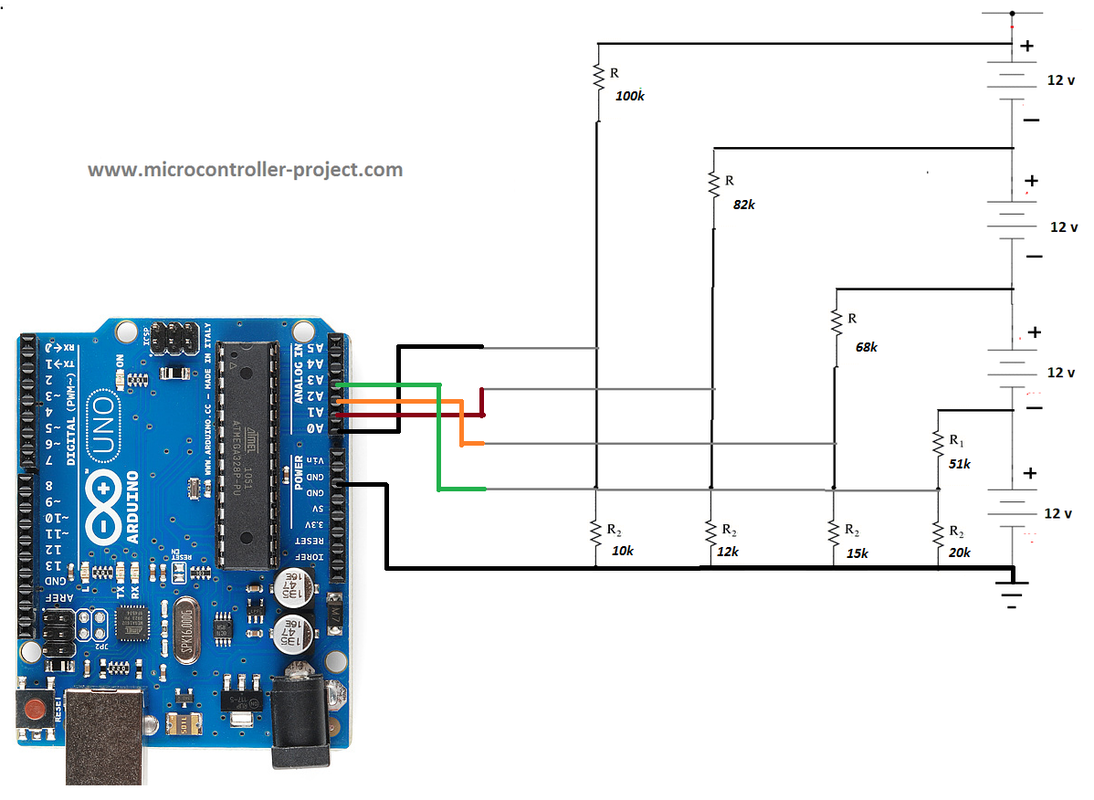

If it is, then you shouldn’t have any significant offset. The Ardunio ground should be tied to the analogue ground of the circuit under test. TV.println(9,85,"TVOut Port By TCPMeta") Just follow the typical pinout for the TVout Library found everwhere on the net.įloat R2 = 10000.0 // resistance of R2 (10K) – see text!

I used 1K and 470ohm resistors like what the library examples on. All you need is are two resistors for the video and sync.
ARDUINO LIPO VOLTAGE MONITOR CODE
Here is the modified code for the Voltmeter to give your project a nice analog retro feel. Would just multiplying the value variable by about 6.67 work instead, as this would essentially equal the input variable? (6.67 because the input to the A0 port = 1.8v, which 1.8*6.67 = the initial input voltage of 12) The reason I ask this is because I would like vin to equal the output voltage after the calculations as I plan to break the given number into 3 separate digits (using modulo). Now, being that I don’t plan to use this code hooked up to an LCD display, I can’t really test this code for myself (though I assume it would work as advertised), though if it’s outputting variable vin, I would assume it would display “Input V = 0.0959.” How does it convert that number to the input voltage as shown in the pictures instead of the above value?

So, the equation used to “decode” the input voltage to the A0 port on the arduino results in 0.0959 (about) from running it through a calculator with value = 1.8v (from 12v source) and R1 + R2 at the default values. Sorry if the answer to this question is completely obvious, I am new to arduino and coding in general. Vin=0.0 //statement to quash undesired reading ! No other protection (for voltage spikes, reverse voltages or higher voltages) is incorporated in this circuit!Īn Arduino DVM based on voltage divider conceptįloat R1 = 100000.0 // resistance of R1 (100K) -see text!įloat R2 = 10000.0 // resistance of R2 (10K) - see text! Keep it in mind that any input voltage higher than about 55V could fry the Arduino.
ARDUINO LIPO VOLTAGE MONITOR DRIVER
16×2 Parallel LCD ( Hitachi HD44780 driver compatible)Īs you may well know, Arduino’s analog inputs can be used to measure DC voltage between 0 and 5V (when using the standard 5V analog reference voltage) and this range can be increased by using two resistors to create a voltage divider.The Arduino board can be powered from a standard 9V battery pack, as usual. It is a simple digital voltmeter, which can safely measure input dc voltages in 0 to 30V range. Here is a useful circuit for Arduino lovers and experimenters.


 0 kommentar(er)
